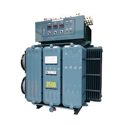
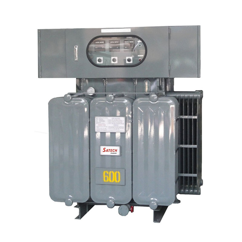
Inductive Voltage Regulator, Oil-immersed Cooling Type
Model:HPI-W Series
Add in inquiry DownloadType:
Oil-immersed Cooling Type
Capacity:
100~6,000KVA
Made in:
Taiwan, ROC
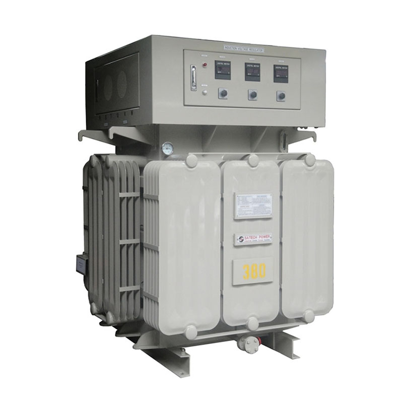
Add in inquiry DownloadType:
Oil-immersed Cooling Type
Capacity:
100~6,000KVA
Made in:
Taiwan, ROC
• Industrial & Manufacturing Plants
• Large Commercial Office Buildings
• Telecom & IT-Data Head Offices
• Government Ministry Buildings
• Ports & Harbor Facilities
• Airports Facilities & Terminals
• Cold Storage Facilities
• Metal Stamping Plants
• Electrochemical Process Plants
• Large & Medium Sized Hospitals
• Flour Mills & Timber Mills
• Water Pumping Stations
• TV Broadcast Head Office
• Cement Manufacturing Plants
Robust, Wear-free, Energy Saving!
► ROBUST DESIGN, WEAR-FREE
BRUSH-LESS. No Sliding Contacts. No Moving Parts to wear out. No Sparks.
Capable of sustaining spikes & Non-linear Load Impulses
► AT LEAST 20 YEARS LONG LIFE SPAN
In addition to its inherently contactless design, by use of high quality materials like Nippon Steel # H14 silicon steel sheets, “PEWC” enamelled wires, DuPont Nomex insulation papers, single phase induction motor and other industrial grade components, and strict quality controlled inspection, at least 20 years life span is warranty under normal operation.
► PRECISE AND LINEAR VOLTAGE REGULATION
Adopt electromagnetic induction working theory to do linear voltage regulation. No contact movement. No tap from the transformer, there is no coupling noise, no boost or sag, to ensure the output voltage accuracy of IVR can be stabilized within a safety working range.
► HIGH RELIABILITY & ENDURABLE, TOLERATE SEVERE ENVIRONMENTS
• Wide Input Voltage Range: ±15% (Option: ±20% ~ 50%)
• >/= 98% VA Efficiency (from 0 to 100% load)
• 0.95 ~1 Input Power Factor
• Low Steel Loss; Low Copper Loss,
• ±1% ~±2% Precise Voltage Regulation Rate
• ADVANTAGES:
a. Improve Plant Performance & Efficiency
b. Increase Facility’s Profitability
c. Increase Equipment Life Span
d. Reduce Production Costs
e. Reduce Maintenance Costs
► SUPER LOAD-CARRYING CAPACITY
• 110% - 1hour; 120% - 30mins;
150% - 15mins; 200% - 2mins;
300% - 12secs; 500% - 6 secs.
• Designed to withstand HEAVY loads Currents
• Designed to withstand HIGH motor Startup / Inrush currents
► FULL ALARMING CAPABILITIES (VISUAL AND AUDIO)
“FAULT” Red indicator will light up and buzzer alarm when IVR is abnormal.
• Current Limit & Circuit Protection
• Loss Phase & Phase Reversed Protection
• Over Voltage & Low Voltage Protection
• Over Temperature Protection
► DIGITAL DISPLAY INPUT VOLTAGE, OUTPUT VOLTAGE, OUTPUT AMPERE
By means of 3-Phase AS / VS Change Over Switch, easily to see Input Voltage, Output Voltage, Output Ampere per each phase.
(Option: Meter with Wide Angle Hanging Wire type)
► SELF DIAGNOSTIC WITH REAL STATUS INDICATORS
When the internal voltage regulating circuit doesn’t work, the IVR will have self-testing, and display the real status with different color indications. It is easy to find fault and troubleshoot the problem.
► MANUAL VOLTAGE ADJUSTMENTS
In case automatic voltage regulation function were failed, change Automatic function to “MANUAL” function, press 『UP』 button when under voltage; press『DOWN』 button when over voltage, in order to have voltage adjustment.
► OPERATION SYSTEM: AUTOMATIC, ELECTRIC AND MANUAL
To ensure the IVR can regulate voltage 24/7/365.
► FREE CONTACTS POINTS FOR ABNORMAL SIGNAL
The front panel of IVR supplies all kinds of abnormal signal (DC5V) for external control.
► CUSTOMIZATION WELCOME
Please contact us, we will welcome the opportunity to review your problems and provide you with necessary solutions.
Robust, Wear-free, Energy Saving!
| MODEL | HPI-W33100 | HPI- W33150 |
HPI-W33200 | HPI- W33300 |
HPI- W33500 |
HPI- W33750 |
HPI- W331000 |
HPI- W331250 |
HPI- W331500 |
HPI- W331750 |
HPI- W332000 |
2100 - 6000K or others, pls ask |
|
| CAPACITY | KVA | 100 | 150 | 200 | 300 | 500 | 750 | 1000 | 1250 | 1500 | 1750 | 2000 | |
| INPUT | |||||||||||||
| Nominal Voltage | 110V, 220V, 380V, 400V, 415V, 440V, 3.3KV, 4.16KV, 11KV, 22KV | ||||||||||||
| Voltage Range | ±15% (Option: ±20%, ±25%, ±30% or others) | ||||||||||||
| Frequency | 47Hz ~ 63Hz | ||||||||||||
| Power Factor | 0.95 ~ 1 | ||||||||||||
| OUTPUT | |||||||||||||
| Nominal Voltage | Same as Input Nominal Voltage | ||||||||||||
| Regulation Rate | ±1% ~ ±2% Adjustable | ||||||||||||
| Response Time | 0.1 seconds after Detection | ||||||||||||
| Total Harmonic Distortion(THD) | < 1% | ||||||||||||
| Efficiency | > 98% at full load typical | ||||||||||||
| Overload | 110% - 1 hour; 120% - 30minutes; 150% - 15 minutes; 200% - 2 minutes; 300% - 12 seconds; 500% - 6 seconds (linear load) | ||||||||||||
| Adjusting Methods | 1) Auto-adjustment, Electro-adjustment, Manual-adjustment; 2) Voltage-UP Time Adjustment (0.1~5 Seconds Adjustable) 3) Voltage-DOWN Time Adjustment (0.1~5 Seconds Adjustable) |
||||||||||||
| Protection (Visual & Audio) |
1) Loss Phase, Phase Reversed (By Voltage Stability Circuit Cut-off) 2) High Voltage 2 Steps Protection: (VR Adjustable): 1St Step: Auto Cut-off Voltage UP Signal to Avoid Voltage Increase ; 2nd Step: Abnormal Indicator 3) Low Voltage 2 Steps Protection: (VR Adjustable): 1St Step: Auto Cut-off Voltage DOWN Signal to Avoid Voltage Decrease ; 2nd Step: Abnormal Indicator 4) Overload Protection (10%~150% Adjustable, 0.1~5 Seconds Adjustable) 5) Over Temperature |
||||||||||||
| Indicator | Input Voltmeter, Output Voltmeter, Output Ampere Meter (Option: Meter with Wide Angle Hanging Wire type or LED Digital Display Type),3-Phase AS/VS Change Over Switch | ||||||||||||
| Coolant | Oil Immersed Cooling Type | ||||||||||||
| Audible Noise | <60dBA at 1Meter | ||||||||||||
| Working Temp. | -20℃ to +45℃ | ||||||||||||
| Relative Humidity | 0-95% (Non-condensing) | ||||||||||||
| Altitude | <4,000 above sea level | ||||||||||||
| Options | 1) Input Over Current Protection (Fused TPN) 100 Amps – 1200 Amps 2) Multi-Function Power Monitoring Unit (Amps / Volts / KVA / KW/ KVAR / Pf) |
||||||||||||
| Rise Temp. | <55℃ | ||||||||||||
| Capacity | 100 | 150 | 200 | 300 | 500 | 750 | 1000 | 1250 | 1500 | 1750 | 2000 |
> 2100 Kva or others, pls ask |
|
| Physical Dimension (WxDxH / mm) |
900 900 1450 |
1000 1000 1550 |
1050 1050 1600 |
1170 1170 1700 |
1270 1270 1870 |
1420 1420 1900 |
1510 1510 1900 |
1700 1700 1900 |
1810 1810 2050 |
1900 1900 2050 |
1900 1900 2050 |
||
| N. W. | kgs | 900 | 1,000 | 1,300 | 1,600 | 2,000 | 3,000 | 3,400 | 4,000 | 4,800 | 5,100 | 5,400 | |
- All specifications are subject to change without notice.
- Custom-made specifications are welcome.
- Cubicle size and weight varies with input voltage range.
TECHNICAL SPECIFICATION (INPUT VOLTAGE RANGE:±25%)
| MODEL |
HPI- |
HPI- |
HPI- |
HPI- |
HPI- |
HPI- |
HPI- |
HPI- |
HPI- |
HPI- |
HPI- |
2100-6000K or others, pls ask |
|
| CAPACITY | KVA | 100 | 150 | 200 | 300 | 400 | 600 | 1000 | 1250 | 1500 | 1750 | 2000 | |
| INPUT | |||||||||||||
| Nominal Voltage | 110V, 220V, 380V, 400V, 415V, 440V, 3.3KV, 4.16KV, 11KV, 22KV | ||||||||||||
| Voltage Range | ±25% (Option: ±15%, ±20%, ±30%, ±35% or others) | ||||||||||||
| Frequency | 47Hz ~ 63Hz | ||||||||||||
| Power Factor | 0.95 ~ 1 | ||||||||||||
| OUTPUT | |||||||||||||
| Nominal Voltage | Same as Input Nominal Voltage | ||||||||||||
| Regulation Rate | ±1% ~ ±2% Adjustable | ||||||||||||
| Response Time | 0.1 seconds after Detection | ||||||||||||
| Total Harmonic Distortion | < 1% | ||||||||||||
| Efficiency | > 98% at full load typical | ||||||||||||
| Overload | 10% - 1 hour; 120% - 30minutes; 150% - 15 minutes; 200% - 2 minutes; 300% - 12 seconds; 500% - 6 seconds (linear load) |
||||||||||||
| Adjusting Methods | 1) Auto-adjustment, Electro-adjustment, Manual-adjustment; 2) Voltage-UP Time Adjustment (0.1~5 Seconds Adjustable) 3) Voltage-DOWN Time Adjustment (0.1~5 Seconds Adjustable) |
||||||||||||
| Protection (Visual & Audio) |
1) Loss Phase, Phase Reversed (By Voltage Stability Circuit Cut-off) 2) High Voltage 2 Steps Protection: (VR Adjustable): 1St Step: Auto Cut-off Voltage UP Signal to Avoid Voltage Increase ; 2nd Step: Abnormal Indicator 3) Low Voltage 2 Steps Protection: (VR Adjustable): 1St Step: Auto Cut-off Voltage DOWN Signal to Avoid Voltage Decrease ; 2nd Step: Abnormal Indicator 4) Overload Protection (10%~150% Adjustable, 0.1~5 Seconds Adjustable) 5) Over Temperature |
||||||||||||
| Indicator | Input Voltmeter, Output Voltmeter, Output Ampere Meter (Option: Meter with Wide Angle Hanging Wire type or LED Digital Display Type), 3-Phase AS/VS Change Over Switch | ||||||||||||
| Coolant | Oil Immersed Cooling Type | ||||||||||||
| Audible Noise | <60dBA at 1Meter | ||||||||||||
| Working Temp. | -20℃ to +45℃ | ||||||||||||
| Relative Humidity | 0-95% (Non-condensing) | ||||||||||||
| Altitude | <4,000 above sea level | ||||||||||||
| Options | 1) Input Over Current Protection (Fused TPN) 100 Amps – 1200 Amps 2) Multi-Function Power Monitoring Unit (Amps / Volts / KVA / KW/ KVAR / Pf) |
||||||||||||
| Rise Temp. | <55℃ | ||||||||||||
| Capacity | 100 | 150 | 200 | 300 | 400 | 600 | 1000 | 1250 | 1500 | 1750 | 2000 |
> 2100 Kva or others, pls ask |
|
| Physical Dimension (WxDxH / mm) |
1000 1000 1550 |
1050 1050 1600 |
1150 1150 1700 |
1280 1280 1900 |
1500 1500 1900 |
1610 1610 2000 |
1700 1700 2000 |
1700 1700 2050 |
1900 1900 2050 |
1900 1900 2050 |
1900 1900 2300 |
||
| N. W. | (kgs) | 1,000 | 1,300 | 1,700 | 2,000 | 3,200 | 3,600 | 4,000 | 4,800 | 5,400 | 5,700 | 6,800 | |
- All specifications are subject to change without notice.
- Custom-made specifications are welcome.
- Cubicle size and weight varies with input voltage range.
► ISOLATION TRANSFORMER
Galvanic isolated is used to protect against electric shock, to suppress electrical noise in sensitive devices.
► MAINTENANCE MANUAL BYPASS
The switch is for periodically maintenance and service. Not affect machinery running in any ways.
► TVSS
Transient Voltage Surge & Spike Suppression Protection against damaging voltage spikes and transients.
► LIGHTING SURGE PROTECTION
Protection against extremely high voltage surges and transients as typical caused by Lightning strikes
on the supply line.
► COMPREHENSIVE DIGITAL POWER METERING & MONITORING
Microprocessor based digital output power meter -- monitoring V, A, W, VAR, PF, W, Hrs & VAR Hrs and offering additional RS-485 output.
► MAINTENANCE BYPASS SWITCHBOARD
Maintenance Bypass Switchboard with inbuilt bypass facility for use with the Stabilizer.
► OUTDOOR APPLICATION
Enclosure: IP-54 or others as per request.
OUR STRENGTHS :
► >/= 85% Semi-finished Products at Stock. Capable to supply the unit in a short time
► Over 30 Years Working Experiences in Magnetic Induction Voltage Regulator.
► Complete Testing Facilities
FACTORY-IN TESTING ITEMS :
• Copper Loss Test
• Steel Loss Test
• No Load Loss & No Load Current Test
• Upper Limit / Lower Limit Switch Test
• Ultra Upper Limit / Ultra Lower Limit Switch Test
• Manual / Electric Adjustment Test
• Insulation Resistance Test
• Withstand Voltage Test (Terminal – Chassis)
• Commercial Frequency Withstand Voltage Test
• Short Circuit Test
• Temperature Rise (Full Load) Test
• Inductive Voltage Test / Layer Short Test
• (200Hz / 400Hz High Frequency Testing for 20secs)
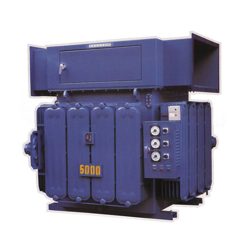
INTRODUCTION :
HPI-D series Inductive Voltage Regulator / Magnetic Induction Automatic Voltage Stabilizer (Brushless / No Sliding Contacts Design) is available from 100 to 5,000KVA as standard, in Single or Three-phase Output configurations.
The HPI-D series Inductive Voltage Regulator pay for themselves.
No matter what the application, variations in voltage can cause considerable loss of time and money.
By reducing unnecessary downtime and costs, the HPI-D series IVR can actually pay for themselves.
What’s more, alternative methods for solving poor voltage problems are usually more expensive than IVRs. Contact your local Satech Power Sales Engineer. He or she will welcome the opportunity to review your problem and help you solve it.
PRINCIPLE :
Inductive Voltage Regulator mainly composes of two structures:
Oil Immersed Magnetic Induction Automatic Voltage Stabiliser (Brushless Design)
This Inductive Voltage Regulator or named as mainly composes of two structures:
1. Mainframe: Inductive Voltage Regulator, initial as IVR.
The Industrial grade Inductive Voltage Regulator is a variable ratio Auto Transformer consisting laminated steel Rotor (called as “R”, the shunt winding) and Stator (called as “S”, series winding).
Functions by the electromagnetic reaction of shaft core with Rotor, to result in relative rotation of both counterparts, thus achieving alteration in the phase of the induced electromotive potential, as seen in a stabilized output.
Transmission is controlled by electric power, whereby Driving Motor is used to drive gear, and alter output voltage which is to be registered in IC chips, once a voltage fluctuation occurs -- going up or down, a command will release to the Driving Motor for adjustment of its phase angle, and that to result in a corresponding change in Output voltage, so that free going voltage regulation is attained without any shifts.
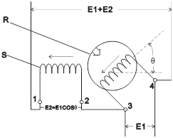
The winding inside Rotor is called Primary Winding (Input), which connects in parallel with input power wire; the Stator is a Secondary Winding (Output) which connects with the same load in series. Secondary Voltage varies with intersecting angle “θ” of both winding. (shown as below figure).
E1 (between 3 and 4) = Input Voltage (Primary Voltage)
(The voltage inducted by the Secondary winding shall vary to the angle between the two coils)
- E2 = E1 cos.θ, vary continuously
- Output Voltage = E1+E2 = E1 (1+ cos.θ)
- When R & S is in parallel, E2 is Increasing (clockwise),
Output Voltage = E1+ (+E2)
Output Voltage = E1 + 0 = E1
- When R & S is in –90deg., E2 is Reducing
(anti clockwise), Output Voltage = E1 + (-E2)
Because of opposite position between Primary and Secondary Winding, output voltage can be adjusted continuously depends on alternation of primary Flux Density even connected with load.
2. Voltage Regulation Structure:
By use of Logic circuits to detect output voltage variation.
When output voltage rate is within +/-1% setting value (1% ~ 3% Adjustable), it will command No Contact Point Relay (SSR) to conduit for no contact point, step-less automatic regulation.
Industrial grade Inductive Voltage Regulator has advantages of
a) No Output Distortion;
b) Pure Sine Wave Output;
c) No Sliding Contacts or Brushes inside;
d) Strong Overload Capability.
It is the only type to be able to fabricate thousands KVA, Powerful Overload Capacity with Minimum Failure Rate.