True Galvanic Isolated On-line UPS (80~160KVA) True Galvanic Isolated On-line UPS (80~160KVA) True Galvanic Isolated On-line UPS (80~160KVA)

True Galvanic Isolated On-line UPS (80~160KVA)

Model:SPU series (80~160KVA)

Type:
IGBT / PWM Type

Capacity:
- Single Phase: 80~160KVA
- Three Phase :
80~160KVA

Made in:
Taiwan, ROC

Add in inquiry Download

• AC Power from vehicle battery

• Communications Systems

• Cellular Sites

• Network & Data Center

• Emergency Lighting

• Medical Systems / Hospitals

• Oil & Gas

• Precise Measuring & Testing Equipment

• Transportation Signaling Power

• High Tech Industry

• TV & Radio Broadcasting Stations

• Utility Applications

• MILITARY APPLICATIONS:

⇒ Military Program, Aircraft,

⇒ Shipboard, Submarine,

⇒ Mobile Power Units, Shelters

⇒ Military System Diagnostics

⇒ Military Research & Defense Weapons

USA Military Approved Power System !

USA MILITARY APPROVED

Quality guarantee!

► HIGH EFFICIENCY, OPTIMUM STABILITY, SUPERIOR HEAT DISSIPATION

By use of advanced Technology DPS, IGBT and Switching Components to increase the reliability, efficiency and heat dissipation.

BUILT-IN AVR FOR WIDER INPUT VOLTAGE RANGE

Input Voltage Range: +/-20% (> +/-20% is available upon request). (AC300V ~ AC520V at 380V Grid, full load mode). Works effectively under any unstable AC source. All of the input components used are specially selected to handle extreme high voltage and high current.

ZERO INRUSH CURRENT

Current Limit Circuit restricts inrush current so oversize cable and wiring is not required.

RELIABLE INPUT PROTECTION

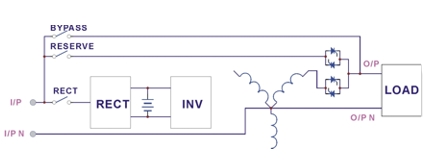
Circuit breakers are placed in each individual input loop to ensure power can continue through another loop in case of breaker trip caused by an abnormal condition in either rectifier or load.

PROTECTION AGAINST DETACHING AND FLOATING OF THE NEUTRAL OF INPUT POWER SUPPLY

An MOV (surge protector) is added at the input, providing protection to both UPS and the load from any lightning surges, or surges caused by neighboring large loads.

EMI SUPPRESSION

An EMI filter is added to meet the international EMC limits. Therefore, very low noise is emitted, and no interference is supplied to other equipment connected to the same AC source.
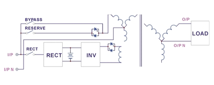
COMPLETE INPUT TO OUTPUT TRUE GALVANIC ISOLATION DESIGN

Solve ultimately power problems, including noise, lightning, ground leakage current, and CEMF (Counter-electromotive Force) etc.


PROTECTION AGAINST MISUSE

Friendly design. The UPS is designed with breaker on/off sensor, power supply sensor, etc. Therefore, any operational mistake made by the user causes no harm to the UPS.

COLD START FUNCTION

Can be started without AC source (with battery only). This is possible because current limit circuitry is added, preventing the problem of large inrush current blowing the battery fuse and damaging the DC capacitors when batteries are connected to an empty DC bus (before the DC bus is energized).

MULTI-CPU DESIGN AND SOFTWARE / HARDWARE COOPERATE CONTROL

Make the system extremely high reliable.
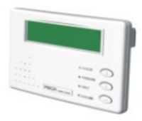
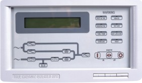
DIAGNOSTIC PANEL WITH LCD AND LED DISPLAY

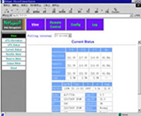
1. Local / Remote System Status available 24/7/365.
Diagnostic Panel with :
• LCD Display real time states, data or historical events, parameters, real time clock, inverter & alarm;
• 24 LEDs representing all of the important information of the user. When abnormal conditions occur, these LEDs will light to warn the user of the cause of the faulty condition , events categorized to alarms and notices

2. Multifunctional Control and Readout

SELF DIAGNOSE, PLUG & PLAY MODULAR DESIGN PCB WITH COLOR MANAGEMENT INDICATORS

All PCBs are Modular design and integrate inside the PCB Holder. In case the SPF series were failed, open the holder, visual inspect the indicator color with beneath descriptions for easy service and quick maintenance.
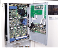
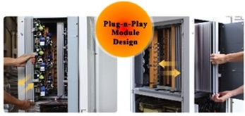
PLUG & PLAY MODULAR DESIGN FOR QUICK MAINTENANCE AND TROUBLESHOOTING

The power circuit is separated into several modules plugged into several slots in the unit, which are easy to pull out, permitting quick maintenance and easier troubleshooting (MTTR < 25minutes).

USER FRIENDLY CONTROL DESIGN

The UPS is designed with breaker on / off sensor, power supply sensor etc. Any operational mistake made by the user causes no harm to the UPS

RUGGEDNESS

The Rectifier employs phase control technology to regulate the DC bus Voltage. This is the most efficient method to charge the batteries.
The SCR used are inherently rugged. Additionally, a large inductor is added at the input to avoid deforming the AC source waveform.

Customizations Welcome

Please contact us, we will welcome the opportunity to review your problems and provide you with necessary solutions.

TOLERATE HARSH ENVIRONMENT

Each component is chosen with large safety margin to accommodate Extreme environments, such as temperature, humidity, altitude, shock or Contamination.

PHASE CONTROL TECHNOLOGY VIA SCR

1. Most rugged design under poor conditions
2. Most efficient method to charge the battery
3. Inductor added at input to avoid fluctuation

EACH PHASE WITH INDIVIDUAL INVERTER SUPPORTING

Characteristics will not be violated under 100% unbalance load.

300% TRANSIENT OVER CURRENT CAPABILITY

ALARM FOR OVER VOLTAGE, OVER CURRENT, OVER TEMPERATURE, OUTPUT SHORT CIRCUIT PROTECTION
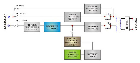
INTELLIGENT CHARGER WITH TEMPERATURE COMPENSATION

Prolong the battery life expectancy. And with huge charging Power (selectable), can charge very big capacity, long back-up time battery bank.

INTELLIGENT, SAFE BATTERY TEST CIRCUITRY

Test the battery without the risk of output AC failure in case of battery bad. And with battery fluid leakage and improper grounding detect circuitry, can ensure safety of the battery bank.

HUGE CHARGING POWER

The charging power is selectable (Lo/Me/Hi) according to Ah rating of the batteries, and can charge up battery banks providing more than 8Hrs back-up time without adding an extra charger.

INTELLIGENT FAN SPEED CONTROL

The fan rotation rate can automatically change according to the load condition, so that the fan’s life expectancy is extended and audible noise is reduced.

REASONABLE HEAT EVACUATION PASSAGE DESIGN

Control circuitry and power circuitry are physically separated. Therefore, the UPS system can operate under harsh environment.
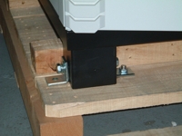
BASE WITH ANCHOR BOLT FIXING

The floor loading capacity should be high enough to endure the weight of the SPF series. The SPF series is mounted on four right-angled steel angles. Insert corresponding bolts and nut 2 (dia.1/2”) into the floor for securing the SPF series on the floor when it is located in an area where earthquakes is possible, or where motion may occur, e.g. vehicle mounted.

3 PHASE INPUT / 3 PHASE OUTPUT (80 - 160KVA)

MODEL

SPU-3380

SPU-33100

SPU-33120

SPU-33160

Capacity 80 KVA 100 KVA 120 KVA 160 KVA

INPUT (RECTIFIER)

Input Voltatge (Select One)

3 Phase 3 Wire+G (Δ): 200/220/380/440/460V (Option:480VΔ / 600VΔ)

3 Phase N+G (Y): 200/208/380/400/415/440V (Option:480VY / 600VY)

Input Voltage Range ± 20% (> ±20% is available upon request)
Input Frequency 50Hz or 60Hz ± 7Hz (400Hz Option) 
Power Walk In 15% ~ 100% : 15 Sec.
Efficiency ≈ 99% 

BATTERY

Battery Type / pieces  Maintenance Free Lead-acid Batteries / 12V x 29pcs
Max. Charge Current Adc (Selectable) 40 A 50 A 60 A 80 A
Battery Start  Yes, UPS can be started without AC Source       

INVERTER

Output Voltage (Select One) 

3 Phase 3Wire+G (Δ): 200/220/380/440/460V (Option:480VΔ / 600VΔ)

3 Phase N+G (Y): 200/208/380/400/415/440V (Option:480VY / 600VY) 
Voltage Regulation Rate ± 1%
Output Wave Form  Pure Sine Wave 
Output Power Factor  0.8 
Frequency Lock Range 45 ~ 55Hz / 55Hz ~ 66Hz (400Hz Option) (Select One) 
Frequency Stability  ±0.1Hz (Crystal Controlled, Free Running) 
Phase Shift 120∘±0.5∘(100% Unbalance Load)
Total Harmonic Distortion < 3% (0~100% Linear Load)
Overload < 100% Continuous
110 ~ 124% 15 Minutes 
125 ~ 149% 5 Minutes 
>/= 150% 30 Seconds 
Efficiency (100% Load)  94.5 % 94.5 % 95 % 95 %

STATIC SWITCH

 
Voltage Range  173 ~ 277 VAC (L-N) (Different voltages are available upon request.) 
Mains ⇔ Inverter 0 ms (True Online) Zero cross transfer

OVERALL CHARACTERISTICS

Capacity 80 KVA 100 KVA 120 KVA 160 KVA
Overall Efficiency 92.5 % 92.5 % 93 % 93 %
Max. Heat Dissipation  4.6 KW 5.4 KW 6.5 KW 8.7 KW
Size (W*D*H / mm)  1100*800*1600 mm     
Weight (KG, W/O Battery) at I/O 380/220V 950 kgs 1250 kgs 1400 kgs 1600 kgs
Audible Noise < 67dBA at 1 meter
Relative Humidity 0%~90% (Non-Condensing)
Temperature 0~40℃(32~104℉)
Altitude <1500M Above Sea Level
Protection Over / Under Voltage, Output Short Circuit, Overload, Over Temperature Protection
Lightning / EMC Filter MOV / Input & Output (FCC CLASS A)
Galvanic Isolation Input and Output True Galvanic Isolation
Diagnostic Panel LCD Display Real Time Status, Historical Events, 24 Status LED Indicators & Alarm
Remote Control

Remote Monitoring 1~99 units simultaneously, distance up to 1,000m

Communication Interface Dry contact, RS232, RS485 (Optional MobBus protocol or SNMP Card) 

STANDARDS 

EMI / EMC  EN50091-1,-2, CE Approved 
UL (Option) ANS/UL1778, 4th Edition, Rev.July 28’06, CAN/CSA C22.2 #107.3-05.Rev.July’06

Remarks:  
1. Different specifications required are available
2. All specifications mentioned above are subject to change without prior notice.


3 PHASE INPUT / SINGLE PHASE OUTPUT (80 - 160KVA)

MODEL

SPU-3180

SPU-31100

SPU-31120

SPU-31160 

Capacity 80 KVA 100 KVA 120 KVA 160 KVA

INPUT (RECTIFIER)

Input Voltatge (Select One)

3 Phase 3 Wire+G (Δ): 200/220/380/440/460V (Option:480VΔ/600VΔ)

3 Phase N+G (Y): 200/208/380/400/415/440V (Option:480VY / 600VY)

Input Voltage Range ± 20% (> ±20% is available upon request)
Input Frequency 50Hz or 60Hz ± 7Hz (400Hz Option) 
Power Walk In  15% ~ 100% : 15 Sec.
Efficiency  ≈ 99% 

BATTERY 

Battery Type / pieces   Maintenance Free Lead-acid Batteries / 12V x 29pcs
Max. Charge Current Adc (Selectable)  40 A 50 A 60 A 80 A
Battery Start   Yes, UPS can be started without AC Source 

INVERTER

 
Output Voltage (Select One) 1 Phase 2 Wire+G: 100 / 110 / 115 / 120V; 200 / 208 / 220 / 230 / 240V (±5% Adj.) (Option: 1 Phase 3 Wire+G)
Output Voltage Regulation ±1%
Output Power Factor 0.8
Frequency Lock Range 45 ~ 55Hz / 55Hz ~ 66Hz (400Hz Option) (Select One) 
Frequency Stability ±0.1Hz (Crystal Controlled, Free Running) 
Total Harmonic Distortion < 3% (0~100% Linear Load)
Overload <110% Continuous
110 ~ 124% 15 Minutes
125 ~ 149% 5 Minutes
>/= 150% 30 Seconds
Efficiency (100% Load) 94.5 % 94.5 % 95 % 95 %

STATIC SWITCH        

Voltage Range 173 ~ 277 VAC (L-N) (Different Voltage are available upon request)
Mains ⇔ Inverter 0 ms (True On Line) Zero cross transfer

OVERALL CHARACTERISTICS

Capacity 80 KVA 100 KVA 120 KVA 160 KVA
Overall Efficiency 92.5 % 92.5 % 93 % 93 %
Max. Heat Dissipation 4.6 KW 5.4 KW 6.5 KW 8.7 KW
Size (W*D*H / mm) 1100*800*1600 mm
Weight (KG, W/O Battery ) at I/O 380/220V 950 kgs 1250 kgs 1400 kgs 1600 kgs
Audible Noise (at 1M) < 67dBA at 1 meter
Relative Humidity 0% ~ 90% (Non-condensing)
Temperature / Altitude  0 ~ 40°C (32 ~ 104°F) / < 1500M Above Sea Level)
Protection Over / Under Voltage, Output Short Circuit, Overload , Over Temperature Protection 
Lightning / EMC Filter MOV / Input & Output (FCC Class A)
Galvanic Isolation Input & Output True Galvanic Isolation 
Diagnostic Panel LCD Display Real Time Status, Historical Events, 24 Status LED Indicators & Alarm
Remote Control / Communication Interface Remote Monitoring 1~99 units simultaneously, distance up to 1,000m / Dry Contact, RS232, RS485 (Option: MODBUS Protocol  or SNMP Card)

STANDARDS

EMI / EMC EN50091-1, -2, CE Approved
UL (Option) ANS/UL1778, 4th Edition, Rev. July 28 '06, CAN/CSA C22.2 #107.3-05 Rev. July '06

Remarks:  
1. Different specifications required are available
2. All specifications mentioned above are subject to change without prior notice.

CUSTOMIZATIONS

► Single and Three Phase Configurations

► 400Hz Input and / or Output Frequency

► Variable Input & Output Power Configurations (60Hz, 50Hz, 400Hz)

► Inline Voltage and Frequency Converters

► 12-PULSE FULL CONTROLLED RECTIFIER

Reduce harmonic current for 80KVA and above SPM series.

► INPUT HARMONIC FILTER

Reduce T.H.D. (Total Harmonic Distortion) of input current.

► SERIAL & PARALLEL REDUNDANT

A supplemental power supply is added to provide redundancy for supplying power to the static switch, so that there will be AC output no matter what happens to the UPS.

► EMERGENCY STOP SWITCH (EPO)

In case of hazard, for example electric shock, fire or earthquake, the UPS can be shutdown (will have no AC at the output) either through a switch (can be added upon request) or through smoke detector signal (can be added upon request) to prevent further injuries or destruction.

► SHOCK MOUNT

The cabinet can be shock mounted using optional rubber or coil type isolators.
This will enable the unit to withstand shock levels as specified in MIL-S-901.

► CASTERS & LEVELERS

For portability, the cabinets may be optionally equipped with the base-mounted casters / leveler set as shown.

► CABLE ENTRANCE DIRECTION

Cable entry can be from Front, Side, Rear or Top side.


COMMUNICATIONS OPTIONS

UPSCANTM - Remote Control Panel

A hand held remote display and control module with LCD and LED display that can monitor up to 99 Frequency Converters via RS-485 at a remote distance up to <1,000M (up to 3,000feet)

GPRS MODEM - Auto-dialing Module

In case of abnormal situation, it will automatically dial to specified service center for help. Multiple phone numbers can be set and no dedicated line is required.

UPSCOMTM - 3 Phase PC Monitoring Software

Can provide real-time three phases information of Frequency Converter connected on the line and monitor 31 Frequency Converters max. with one PC.

3 Phase SNMP Card

Can monitor and manage the Frequency Converters through Web browser and Java applet, providing simultaneously three phases data acquisition.

► DCMANTM - Battery Monitoring Module

An intelligent module to keep watching each battery in a battery bank connected in series and can distinguish and repair the aged battery before it is seriously worn out.

What is "True Galvanic Isolation"?


Usually, Y-caps are installed in UPS’s input & output to eliminate the electro-magnetic interference, but Y-caps will increase the ground leakage current. Together, with the parasitic capacitance of the unit itself the impedance between power lines and ground becomes very low. Therefore, the grounding quality will be affected, resulting in voltage differences between different systems, and problems will arise, such as the connection terminal sparks when plug in the communication port, or the data transmission seriously interfered. The whole LAN system will be contaminated or even computers (equipments) will be destroyed.

The best way to prevent and solve this problem is to completely isolate the UPS output from the input power system. In that case, the UPS output can be tied to any ground at any potential. Not only the noise inside the UPS is stopped, and the output neutral can adapt to any voltage induced by complicated connection of the load system, but also can stop the electro-magnetic interference, surge, and spikes caused by lightning or heavy / inductive load impact / detach nearby, comes through the UPS to the load. Beside, output can remain safe even when neutral is disconnected. Now, protections against over-shoot voltage are explained below.


Comparative System Diagram

Fig 1: SPU True Galvanic Isolated UPS

Fig 2: Non-true Galvanic Isolation