The Most Advanced & Intelligent IVR!
► ULTRA WIDE INPUT VOLTAGE RANGE
115V to 280V Ultra Wide input voltage range design. IVR can work in normal even at the worst input voltage range. All components have been strictly selected which are able to resist transient surge & huge current.
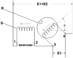
► PRECISE & LINEAR VOLTAGE REGULATION
Adopt electromagnetic induction working principle to do linear voltage regulation. No contact movement; no noise coupling; no boost or sag, to ensure power quality of load remains the same as the input.
► STURDY, DURABLE, LONG LIFE SPAN
No Sliding Contacts. Brush-less. No Sparks. No Components to wear out. Capable to
sustain spikes & non-linear load anti-electric feedback. High Reliability and Long Life Span.
► ADVANCED FULL PROTECTION WITH BUZZER ALARM & INDICATORS FLASHING
When output voltage is out of range, overload, short circuit, phase failure, phase reversed, over temperature or abnormal control circuit, the output will be cut off automatically, buzzer alarms and LED indicators is flashing.
► SURGE AND LIGHTNING PROTECTION
Surge suppressor and / or Lightning Arrestor are built-in. Capable to absorb transient surge voltage from power grids.
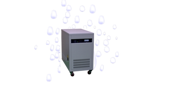
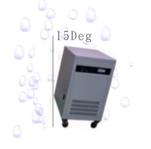
► HARSH ENVIRONMENT DESIGN
Composed of high efficiency and wide safety range of industrial grade components, the IVR can sustain severe temperature, humidity, vibration and dirty environments.
► SOFT START WHILE AUTO RESTORE FROM AC POWER RECOVERY
Instantaneous power blackouts and restore will damage electrical loads. While AC power recovery, the IVR starts automatically from low voltage output, to ensure the security of load.
► STRONG OVERLOAD CAPABILITY
The IVR will not be damaged when short circuit happened on the loads or over current in transient. 150% / 90seconds, 200% / 20seconds, 300% /10seconds.
► LOW POWER LOSS. HIGH EFFICIENCY
Low Iron loss silicon steel sheets, oxygen-free enameled wires, they help the voltage regulators develop high performance, less power loss.
► SELF-DETECT REGULATOR SYSTEM
When the internal voltage regulating circuit doesn’t work, the IVR will have self-testing.
► MASTER CIRCUIT & SLAVE CIRCUIT INTERLOCKED PROTECTION
The IVR have circuit interlocked protection of voltage regulating circuitry and monitoring control circuitry.
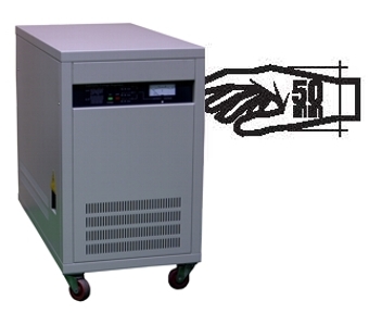
► FAST RESPONSE TIME
< 50 millisecond
► AUTOMATIC BYPASS OUTPUT
The IVR with Automatic Bypass function. When the output voltage is abnormal, when the input voltage is within the setting range, the IVR will switch automatically to bypass, no manpower to operate.
► PASSWORD TO OPEN THE DOOR FUNCTION
The IVR requires a password to open the door locks, no key, just enter your password on the touch screen and open the front door of the IVR.
► FULLY ISOLATED MANUAL BYPASS
When the IVR is failed or required maintenance in Bypass mode, it can changeover the Double Throw Bypass Switch manually to mains through the load. The IVR remains overload and short circuit protection in Bypass mode. To ensure the IVR stability, voltage regulator circuit and protection circuit are detected by use an independent power supply
in order to avoid electrical fault, causing malfunction.
► LCD TOUCH PANEL DISPLAY
Intuitive Touch Panel to show system descriptions, System Status, loading Status, System Settings, Event Logs. Option: Big LCD display to show input voltage, output voltage, output current and IVR status.
► RS485 COMMUNICATION INTERFACE FUNCTION
The IVR with RS-485 communication interface, via MODBUS communication protocol, users can design their own software, monitor the parameters of AVS through the computer at any time.
► HISTORY EVENTS FEATURE
The IVR with History Events function, you can always check the IVR of the history of working time, including System On/Off, Abnormal Conditions, Bypass / Voltage Regulation, Open / Close the front door and so on.
► EXTERNAL DRY CONTACTS FOR ABNORMAL SIGNAL
The front panel of IVR provides all kinds of abnormal signals (DC5V) for external control.
► MULTI-LAYER TYPE CIRCUITRY CONTROL
To ensure its reliability, all separate PCBs (voltage regulation, protection, monitoring & control,
drive circuit board) are isolated from each other.
► CPU CONTROLLED
► CUSTOM-MADE WELCOME
Listen and design to meet with your demands.