IVR / Variac, Oil Immersed Cooling Type IVR / Variac, Oil Immersed Cooling Type IVR / Variac, Oil Immersed Cooling Type IVR / Variac, Oil Immersed Cooling Type IVR / Variac, Oil Immersed Cooling Type IVR / Variac, Oil Immersed Cooling Type IVR / Variac, Oil Immersed Cooling Type

IVR / Variac, Oil Immersed Cooling Type

Model:HPI-O Series

Type:
Oil-immersed Cooling Type

Capacity:
- Single Phase: 10~2,000KVA
- Three Phase: 10~10,000KVA

Made in:
Taiwan, ROC

Add in inquiry Download

• Withstand Voltage Test

• Transformer Characteristic Test

• DC Motor Control Speed

• Chemical Manufacturing

• Metallurgical Industry

• Electrical Manufacturing

• Pump

• Test Benches

• Home Appliance Temperature Control

• Step-less Output Voltage Adjustment of Transformer

• Step-less Adjustment for the Voltage to be used in

• Various Industrial Machinery on Loading

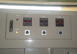
100% Step-less Voltage Adjustment during Loading!

ROBUST, WEAR-FREE, LONG LIFE SPAN

1) No Contact Points (BRUSHLESS), Wear-free.

2) 100% Step-less Voltage Adjustment during Loading.

3) 20 Years at least life span.

ELECTRIC (AUTO) & MANUAL ADJUSTING CONTROL METHODS

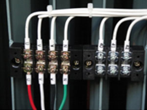
1) Remote Control Terminal Connection

2) Upper Limit & Lower Limit Contact: 1A1B 5A

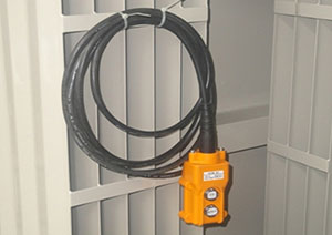
3) Voltage-Up & Voltage-Down Push Button with 3M length cable for operation

FULL ALARMING CAPABILITIES (VISUAL AND AUDIO)

1) Upper Limit & Lower Limit c/w 2 Stages Protection for Auto Shutdown Protection

2) If the Upper Limit & Lower Limit fails, Ultra Upper Limit & Lower Limit will cut off automatically
3) IVR c/w Upper Limit Contact & Lower Limit Contact for external connection of the Lower Limit start-up, Indications of Upper Limit & Lower Limit

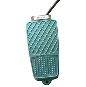
4) Micro Switch: Japan-made Omron Z-15GW-B

HIGH RELIABILITY

Strict QC before ex factory to bring high quality.

Manual / Electric Adjustment Test, Insulation Resistance Test, Short Circuit Test, Temperature

Rise (Full Load) Test, Inductive Voltage Test, Upper Limit / Lower Limit Switch Test, No Load

Loss & No Load Current Test, Commercial Frequency Withstand Voltage, Withstand Voltage

Test (Terminal – Chassis)

EXCELLENT PERFORMANCE

By use of Japan-made high flux silicon steel plate to reduce no load loss, loading loss, no load current to minor, bring up the following advantages:

1) Improve Plant Performance & Efficiency

2) Increase Facility’s Profitability

3) Increase Equipment Life Span

4) Reduce Production Costs

5) Reduce Maintenance Costs

EASY MAINTENANCE & SERVICE

Almost zero free maintenance. Just keep it clean, no other special maintenance.
Modular design. All components have been standardized, easy for maintenance and repair.

SUITABLE FOR HIGH POWER CAPACITY

Magnetic Induction type is the only stand-alone system can be manufacture up to 10,000KVA.

CUSTOMIZATION WELCOME

Please contact us, we will welcome the opportunity to review your problems and provide you with necessary solutions.

• 3 PHASE INPUT 1 PHASE OUTPUT

• 1 PHASE INPUT 3 PHASG OUTPUT

sales@satechpower.com

• Input Voltmeter

• Output Voltmeter

• Output Ammeter

• Min & Max Voltage Indicators


• Voltage-Up & Voltage-Down Push Button with 3M length cable for operation


• Upper Limit & Lower Limit Contact: 1A1B 5A


• EPO Switch: For Emergency Brake

INTRODUCTION :

The HPI-O series Variable Transformers / Slidac / IVR / Magnetic Induction Automatic Voltage Regulator (Brushless, No Contact Point Design) are available from 10 to 10,000 KVA as standard, Single Phase system from 10 to 2,000KVA; Three Phase system from 10 to10,000KVA. Standard models include input voltages from 110V, 220V, 380V, 440V, 3.3KV,11KV, 22KV. Special units for other voltages are available on order. They are categorized by their input voltage, output voltage and number of phases.
If you do not find the Variable Transformers / Slidac / IVR that meets your application requirements, please contact us with your detailed specifications.

While today there are many modern alternatives to the Variable Transformers / Slidac / IVR for controlling voltage, the load tolerant nature of the Variable Transformers / Slidac / IVR ensures that it is still the best and most reliable method of control for a large variety of applications where step-less control of a distortion-free AC output and dependent parameters are essential. Typical uses include quality control testing, electronic equipment burn-in, low voltage performance evaluation, DC rectifier / regulator analysis or other industrial and engineering applications. Our endurable ranges of Variable Transformers / Slidac / IVRs all deliver an efficient and trouble free method of varying AC voltages with an output from zero to line voltage.


PRINCIPLE :

The Inductive Voltage Regulator is a variable ratio Auto Transformer consisting laminated steel
Rotor (called as “R”) and Stator (called as “S”)
Functions by the electromagnetic reaction of shaft core with Rotor, to result in relative rotation of both counterparts, thus achieving alteration in the phase of the induced electromotive potential, as seen in a stabilized output.

Transmission is controlled by electric power, whereby Servo Motor is used to drive gear, and that transmitted to the shaft core to bring about a change in output voltage which is to be registered in IC chips, so that once a voltage fluctuation occurs, going up or going down, an instruction will be released, going to the Servo Motor for adjustment of its phase angle, and that to result in a corresponding change in Output Voltage, so that free going regulation of voltage is attained without any shifts.

The winding inside Rotor is called Primary Winding (Input). The winding of Stator, in parallel with mains power line, is called Secondary Winding (Output). It is in redundant with the load.
Secondary Voltage varies with intersecting angle “θ” of both winding. (as below draft)


- E1 (Between point 3 and point 4) = Input Voltage (Primary Voltage)
(The voltage inducted by the secondary coil shall vary according to the angle between the two coils)
- E2 = E1 cos.θ
- Output Voltage = E1+E2 = E1 (1+ cos.θ)
- When R & S is in parallel, E2 is Positive, Output Voltage = E1+ (+E2)
- When R & S is in 90deg., E2 = 0, Output Voltage = E1 + 0 = E1
- When R & S is in –90deg., E2 is Negative, Output Voltage = E1 + (-E2)

Because of opposite position between Primary and Secondary Winding, output voltage can be adjusted continuously depends on alternation of primary Flux Density even connected with load.
Inductive Voltage Regulator has advantages of
a) No Output Distortion;
b) Pure Sine Wave Form Output;
c) No Sliding Contacts or Carbon Bushes inside;
d) Strong Overload capability.
The only type to be able to fabricate thousands KVA, Powerful Overload Capacity with Rare Faulty Rate.


FACTORY-IN TESTING ITEMS :

• Manual / Electric Adjustment Test

• Insulation Resistance Test

• Short Circuit Test Switch Test

• Temperature Rise (Full Load) Test

• Inductive Voltage Test / Layer Short Test

(200Hz / 400Hz High Frequency Testing for 20secs)

• Upper Limit / Lower Limit Switch Test

• Ultra Upper Limit / Ultra Lower Limit

• No Load Loss & No Load Current Test

• Withstand Voltage Test (Terminal – Chassis)

• Commercial Frequency Withstand Voltage Test